The concept of the Gate-Rudder is clearly deviating from other conventional rudder systems. Single screw vessels have in general the rudder placed behind the propeller, where the movable part can be a part (semi-spade) or the complete rudder section (full-spade). The rudder profile sections can be pre-aligned with the incoming flow (twisted leading edge) or straight. On the other hand, the Gate-Rudder concept comes with 2 symmetrical rudder parts, which are placed on both sides of the propeller. The downstream, accelerated flow will thus not directly interact with the rudder.
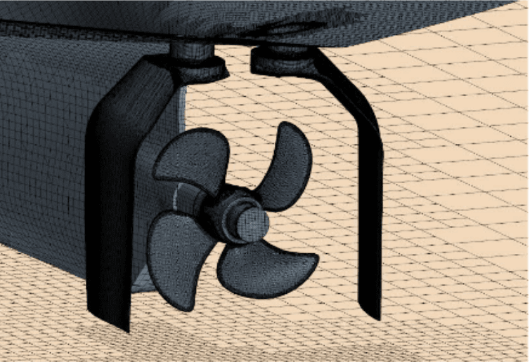
Design of the rudder-sections targets at a stagnation point of the flow close to the outer-side of the rudder leading edge. As a consequence, a low-pressure region is created on the inner side of the Gate-Rudder, which creates a net-thrust force. Second effect of this concept is a large inward oriented force. As long as both rudder-parts are positioned at the same steering angle, the two inward force-components compensate each other. Once a small ruddersteering action is executed, the force-balance shifts, which results in the desired side-force to steer the vessel. The Gate-Rudder concept can thus be compared to a kind of pre-tensioned system. Figure 1 shows a picture of the Gate-Rudder concept with a CCP propeller, where the two symmetrical rudder-parts are clearly visible. More details on the concept and results from a comparison of two sister-vessels with conventional and Gate-Rudder can be found in paper by Sasaki et al [1].
References
1. Sasaki,N., Kuribayshi, S., Bulten, N, Yazawa, M., ‘Joint sea trial of ships withGateRudder and conventional rudder’, Full Scale ship performance onlineconference, RINA, February 2021
D6.3 Gate-rudder CFD model
For decades, early performance evaluation of vessels, propulsion devices, and rudders in the marine industry has been based on model-scale tests in towing tanks. In recent years, computing power and software have developed to the point where performance evaluations based on computer flow simulations are a good alternative.
Three distinctive tests are executed for typical model-scale vessel-powering experiments: Bare-hull resistance runs, propeller open-water performance runs and vessel-self-propulsion runs. For the CFD simulations, this approach can be followed, although some subtle differences in the approach can also be implemented. For this purpose, a numerical calculation method for the determination of the hydrodynamic performance of a vessel is described. The so-called In Silico method is based on viscous flow simulations, which can provide proper estimations of required power to operate a vessel under certain conditions. The flow simulations are based on full-scale hull dimensions, which is a fundamental difference from model-scale testing, since the model-scale tests require semi-empirical extrapolation methods to get full-scale predictions.
In the report D6.3 the concept of the Gate-Rudder was discussed in more detail, also addressing the vessel operating conditions which were to be considered in the numerical flow simulations. Given the scope of conditions, with both straight sailing conditions and vessel manoeuvring conditions, a choice for a consistent numerical approach was made. The detailed description of the applied numerical method, with motivation for the made choices was given and with discussing the required post-processing steps to turn the data from the numerical results into a proper data set of results. CFD flow-simulations are used to investigate effects of the use of a gate rudder setup for both case vessel types. Various operating conditions are considered for the performance evaluation and results are fed in the CHEK modelling.
Implementation of Wind-Assisted-Ship-Propulsion (WASP) devices and hull roughness are possible within the method. Trends from this analysis can be used to make a first estimate of the impact of energy saving devices for a range of vessel speeds and different propeller loading conditions.
D6.4 Meraviglia and Kamsarmax hull design 3D models
In addition to the other key technologies gate rudder, air lubrication and ultrasound antifouling, optimising and creating alternative hull forms from existing hull forms offers an option to reduce existing propulsion power requirements. This contributes to the increase in the overall efficiency of the case vessels and thereby reduces GHG emission.
Reference hull forms were recreated in 3D software using available information of the case vessels. To prove that the existing propulsion power requirements can be reduced by optimisation alone, alternative hull forms were created. State-of-the-art RANSE code methods were used to calculate calm water resistance and corrections for added resistance in waves were also applied. Models were created to simulate interactions with other CHEK technologies, wind sails, air lubrication, and anti-fouling.
By modifications of the hull form the results show that an improvement of 2,2% to 5% for the bulk carrier and 0,5% to 1,2% for the cruise ship can be achieved. Rigid sails were also tested and found to provide a 9% to 14 % improvement. Models were created and first estimates were made for the other CHEK technologies.
The work will continue as an integral part of Digital Master development in order to verify if further improvements are possible with other CHEK technologies, such as gate rudder. It should be noted that weather routing to find better winds would increase the savings due to sails optimistically. This is not included in the present calculations. According to initial estimates, the importance of fouling seems to be quite high.
D6.6 Gate-Rudder™ performance estimate of the different aspects based on full- scale CFD simulations
The CHEKproject has explored the novel Gate-Rudder™ concept, involving two rudderblades positioned alongside the propeller, through comprehensive full-scaleComputational Fluid Dynamics (CFD) simulations. This analysis has primarilyfocused on the Bulker vessel, evaluating the Gate-Rudder's performance insynergy with Wind-Assisted-Ship Propulsion (WASP) technologies. The findingsreveal that the Gate-Rudder's benefits vary significantly with operatingconditions, offering modest advantages in calm, straight sailing but increasingsubstantially under vessel drift and varied steering angles due to enhancedsway force and yaw moment generation.
The projectextended its analysis to both single-screw and twin-screw configurations, wheretwin-screw setups incorporate four Gate-Rudder blades, enabling thrustvectoring to manage a full 360˚ sector, enhancing maneuverability. This featureis particularly beneficial in low-speed "crabbing" operations andduring critical maneuvers like crash-stopping, where the Gate-Rudderscontribute to negative thrust, improving stopping performance.
Forsingle-screw vessels, the Gate-Rudder equipped with a Controllable PitchPropeller (CPP) demonstrates comparable performance to conventional rudders instraight sailing but offers reduced drag penalties and better handling underside forces. The twin-screw variant, while facing challenges from unexpectedpropeller-hull interactions leading to increased hull resistance, showspromising results in terms of rudder load balancing and overall sway forcemanagement, suggesting a potential for non-symmetrical blade designs forenhanced efficiency.
Theinteraction with WASP indicates that the Gate-Rudder maintains steadysway-force production even with reduced propeller load, allowing for moreefficient operation with lower rudder angles and thus reducing overall drag.The twin-screw crabbing operation further highlights the design's versatility,enabling fine-tuned control of surge and yaw forces, advantageous duringberthing operations, particularly in windy conditions.
Overall,the project underscores the Gate-Rudder's advanced capabilities in enhancingmaneuverability and efficiency, especially when integrated with otherpropulsion aids like WASP. Continued research is recommended to optimize designelements such as blade asymmetry and to evaluate performance across a broaderrange of operational conditions to fully capitalize on this innovativeconcept's potential benefits.